

Selecting the right three way ball valve actuator is a critical decision that dictates the safety, speed, and precision of your fluid handling system. On high-stakes skids or fuel manifolds, choosing the wrong drive method can lead to unintended cross-port contamination or pump deadheading, ruining production and increasing repair costs.
While the L-port or T-port configuration defines your flow path, the actuator determines how reliably that flow path is executed. This guide provides clear selection logic for B2B buyers to match the right technology to their specific industrial requirements.

1. Manual Three Way Ball Valves
Manual actuation remains the most robust solution for systems where flow paths rarely change.
- Best For: Low-frequency switching, seasonal tank switching, and bypass isolation. It is the ideal choice for remote installations because it requires no electrical wiring or air lines.
- Not Recommended For: High-frequency automation or processes requiring remote feedback. Because it requires a physical operator to verify the ball’s position, it increases the risk of human error in complex manifolds.
2. Electric Three-Way Ball Valves
Designed for “smart” instrumentation, electric actuators provide the highest level of precision for modern process automation.
- Best For: Facilities requiring remote operation from a central station and integration with SCADA systems. They are the best choice for modulating control, essential for maintaining viscosity in additive lines through precise flow blending.
- Technical Advantage: Electric actuators provide continuous position feedback, allowing operators to monitor valve status remotely and detect faults before they interrupt production.
- Not Recommended For: Emergency situations requiring rapid response, as electric motors typically take 15–30 seconds to cycle.
3. Pneumatic Three-Way Ball Valves
In heavy-duty industrial settings, pneumatic actuators are the standard for high-speed, high-reliability requirements.
- Best For: Applications requiring rapid cycle times (1–2 seconds) for emergency diverting and installations in hazardous areas. They are the preferred solution for systems requiring a mechanical spring-return fail-safe to move the valve to a safe position during power loss.
- Technical Advantage: Their simple mechanical design delivers excellent reliability in continuous-duty industrial environments with frequent cycling.
- Not Recommended For: Facilities lacking a dedicated, reliable compressed air infrastructure.
Manual vs. Electric vs. Pneumatic: Comparison Table
| Feature | Manual Lever | Electric Actuator | Pneumatic Actuator |
|---|---|---|---|
| Power Source | Human Effort | Electricity (AC/DC) | Compressed Air |
| Cycle Speed | Manual/Variable | 15–30 Seconds | 1–2 Seconds |
| Fail-Safe | No | Battery (Optional) | Spring Return |
| Feedback | Visual Only | SCADA / Digital | Limit Switches |
| Automation | None | Excellent | Excellent |
| Hazardous Area | Moderate | Explosion-proof required | Excellent |
| Maintenance | Low | Medium | Medium |
Step-by-Step Actuator Selection Guide
Follow these five steps to determine the correct configuration for your manifold:
Step 1: Determine the Required Control Method
Decide if your process allows for manual intervention or if it requires automated sequences.
Step 2: Check Available Utilities
Evaluate your installation site. If the location is remote with no power, a manual lever is your baseline. If the facility is fully automated with a control room, an electric actuator is likely the best choice. If you have a reliable “house air” system, pneumatic is the logical choice.
Step 3: Define Speed, Automation, and Safety Requirements
Determine if you need the valve to cycle in under 2 seconds for safety. If a mechanical fail-safe is required to return the valve to a “safe” port position during a loss of power or air, prioritize a pneumatic spring-return actuator.
Step 4: Evaluate Operating Environment and Media
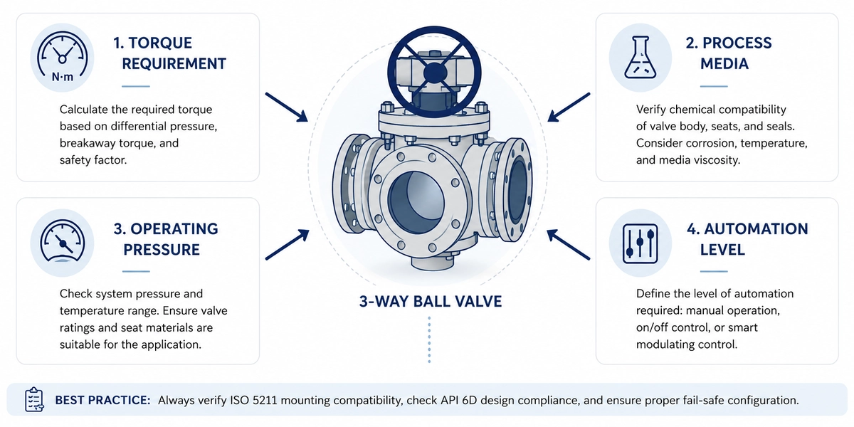
Account for the chemical nature of the media, often requiring 316L stainless steel for corrosion resistance, and whether the area is classified as hazardous. Check the pressure-temperature curve of the PTFE seats.
Step 5: Verify Valve Compatibility
Ensure the valve body features an ISO 5211 mounting pad for direct assembly. Size the actuator based on the valve’s maximum breakaway torque, modified by a suitable safety factor to prevent the ball from stopping mid-rotation.
Common Pitfalls to Avoid
- Neglecting Breakaway Torque: Sizing an actuator without accounting for maximum torque, especially in high-pressure or viscous fuel applications, can cause the ball to stall, leading to seat damage.
- Improper Limit Switch Calibration: Failing to calibrate switches correctly leads to “cross-port seepage” where media bleeds into unintended outlets.
- Ignoring Safety Standards: Always cross-reference hardware against API 6D design standards and API 607 fire-safe certifications.
The ONERO Advantage
Since 1986, ONERO has specialized in manufacturing API-certified ball valves backed by rigorous testing. Their engineering team uses valve torque testing stands and coordinate measurement machines to verify dimensional accuracy and pressure performance. For pipeline cleaning and product separation applications, ONERO also offers pigging ball valves designed to maintain flow integrity during pigging operations. Choosing an experienced manufacturer helps improve system reliability while reducing long-term maintenance costs.
Conclusion
Selecting the right three way ball valve actuator depends on balancing automation requirements, operating environment, and system safety rather than focusing on a single feature. By understanding your control requirements, available utilities, operating environment, and safety expectations, buyers can confidently select the most suitable actuator for their application.
Manual actuators provide simplicity for infrequent operation, electric actuators excel in automated systems with precise control, and pneumatic actuators remain the preferred solution for rapid cycling and hazardous environments. By matching the actuator to your application and verifying compatibility with ISO 5211 mounting standards and API-certified valve designs, you can improve system reliability while minimizing maintenance and downtime.
FAQ
What is the difference between an L-port and a T-port three-way ball valve?
An L-port valve diverts flow between different outlets, making it suitable for switching applications. A T-port valve can connect multiple ports simultaneously, allowing it to mix or distribute flow across different process lines.
How do I determine the correct actuator size?
Actuator sizing should be based on the valve’s maximum breakaway torque, operating pressure, media characteristics, and an appropriate safety factor. Proper sizing ensures reliable operation and prevents the actuator from stalling during valve rotation.
Can electric actuators be used in hazardous areas?
Yes, but only when the actuator is specifically certified for hazardous locations. In many industrial environments, pneumatic actuators are preferred because they operate using compressed air and can provide reliable fail-safe operation.


